Over the years, I’ve noticed that pilots tend to give insufficient attention to two critical airframe elements: tires and props. I’ve already covered tires, so today let’s look at the perils of improper maintenance on a constant-speed propeller.
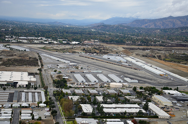
On January 23, 2003 at about 4:20 p.m., Rob Cable — the grandson of Cable Airport founder Dewey Cable — took off from that airfield to perform a post-annual test flight in his twin-engine Beech 95 Travel Air. Six minutes later he was killed when the Beechcraft crashed in Rancho Cucamonga.
This accident was big news in the Southern California flying community. Cable Airport bills itself as “the world’s largest family-owned public-use airport” and anyone who’s been there can tell you what a scrappy little place it is. From the friendly people to the quirky Maniac Mike’s Cafe to the gently rolling terrain that seems to encompass every bit of the airfield, a trip to Cable always reminds me of what general aviation can — and should — be.
The NTSB investigation soon found that the cause of the accident was a mechanical failure. This alone made the crash significant. Statistics point to pilot error outweighing mechanical failure as the root cause of fatal accidents by a ratio of about 9-to-1.
In this case, it was determined that a 2.5 foot-long portion of one of the right engine’s propeller blades had failed. Think about that for a moment. This aircraft was equipped with two-bladed props, each of which had a diameter of about six feet. Therefore each blade was about three feet long. Losing 2.5 feet of a blade meant that the hub was now attached to a three-foot blade on one side and a broken 6″ stub on the other. Can you imagine the difference in weight between the two sides of the propeller?
According to the NTSB, the resulting imbalance cause a vibration severe enough that it overstressed the engine mount and tore the right engine off the airframe. A witness reported “reported observing the right engine hanging straight down toward the ground with the propeller stopped”. At that point the center of gravity would have rendered the aircraft uncontrollable.
It should be noted that while this was a massive failure, I’ve seen cases of props shedding just an inch or so off a blade tip causing such severe vibration that instruments in the cockpit were shattered, cowlings were torn away, and other serious damage was created.
One of the most famous constant-speed prop failures occurred during a test flight of the the Rutan Voyager in 1986. A blade broke off the rear engine near the prop hub. Voyager was equipped with composite propellers with blades which were much lighter than the metal Hartzell unit on Rob Cable’s Travel Air. Dick Rutan later wrote that after figuring out which engine had the problem, he moved the mixture control to the cut-off position. As the rear engine slowed down, the amplitude of the vibration increased, eventually tearing the powerplant completely off it’s mount. Those engine mounts were designed to handle 10g, so you can imagine the forces at work. Rutan said that after landing at Edwards Air Force Base, they found the engine lying on the bottom of the cowling, attached only by a safety cable they had installed for just such a purpose.
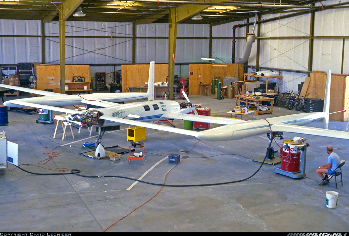
In Voyager’s case, the MT propellers were so troublesome that they were soon replaced with more traditional metal props specially manufactured by Hartzell (in record time — something the folks at Hartzell are still proud of) with specially shaped blades. The increase in aerodynamic efficiency more than made up for the increase in weight, and the program went on to successfully circumnavigate the planet on a single tank of gas.
Anyway, back to our story. The NTSB delved into the Travel Air’s maintenance records and found that, rather than being neglected as one might expect, the props had just been overhauled! Their next stop was the FAA-approved Repair Station that did the work, T&W Propeller in Chino. This is where things got particularly interesting for me, as I owned an aircraft with a constant-speed prop that had just been overhauled by that very same shop.
You can read the full report if you’re so inclined, but here’s just a partial list of what was found on the accident airplane’s propellers:
During the Hartzell participant’s teardown examination he made a series of observational findings. He observed the following discrepancies between the overhaul procedures specified by Hartzell in its maintenance manuals and the physical evidence found in the propellers:
1. The blade internal bores were clearly not in compliance with overhaul requirements for inspection, rework, and finishing. There was no paint and there appeared to be no chemical conversion coating in the bore area. There was extensive corrosion in the internal bearing bore area A, as defined by Hartzell Service Bulletin 136H. The participant stated that a proper overhaul requires removal of the blade bronze bushings in order to accomplish rework and inspection.
2. The hub arm of the right propeller had cadmium plating on top of deep corrosion pits. Such corrosion is required to be removed during overhaul.
3. A blade clamp in the right propeller had cadmium plating on top of deep corrosion pits. Such corrosion is required to be removed during overhaul.
4. Blades from the left propeller were too long. The aircraft is approved for installation of a propeller having a diameter of 72 to 70 inches. The length of blade L1 was measured to be approximately 32-5/8 inches long, which corresponds to a 74-inch diameter. Blades from the right propeller were measured to be approximately 31-5/8 to 31-3/4 inches, which is the correct length and corresponds to a 72-inch diameter.
5. Blades from the left propeller were impression stamped 8447-4 and 8447-12, and should have been stamped 8447-12R. Blades from the right propeller were impression stamped 8447, and should have been stamped 8447-12A.
6. Remnants of phenolic washers were found in the left propeller. The washers were approximately 1 to 2 inches in diameter and installed over the hub pilot tube, between the hub arm and blade butt of both blades. These were not Hartzell parts and such usage is not authorized.
7. Small particles, which appeared to be plastic cleaning media, were found in the grease in the blade balance hole.
8. The cadmium plating on the blade clamps and hubs was unusual. While much of the surfaces had bright cadmium plating, there were numerous spots that had no plating, areas of dull gray appearance, and areas that appeared worn. Portions appeared to have either deteriorated plating or had not been plated. Given the report that the propeller had only 5 hours of operation since overhaul, the general condition of the cadmium plating was considered very poor.
9. One O-ring, used as a seal between the clamp and hub was severely deteriorated. It had many cracks around the circumference of the outside diameter. The other three blade clamp O-rings were in good condition. It appeared that the deteriorated O-ring had not been replaced during overhaul.
In conclusion, the Hartzell participant made the following statement regarding the observed overhaul procedure discrepancies: “The most significant discrepancy was the presence of obvious, significant corrosion in the internal bearing bore area of the blades. This, plus the absence of required corrosion protection (chemical conversion coating and paint) in this area, clearly indicates that proper overhaul was not accomplished.”
Even if you don’t speak “A&P”, the gist is undoubtedly clear: T&W Propeller was criminally negligent in the performance of their work and it resulted in a fatal accident. The FAA quickly issued Airworthiness Directive 2003-13-17, which required another overhaul of my improperly zero-timed constant-speed prop. I believe the price tag for the two overhauls was nearly $6,000. Welcome to the world of aviation! It reminds me of an old joke where a prospective student pilot asks a grizzled veteran how much money it would take if he wanted to learn to fly. The answer: “All of it.”
It was about this time that I realized that the “FAA Certified Repair Station” designation means absolutely nothing. I sent the prop to a small, non-CRS shop in Bakersfield called Johnson & Sons and got a better result for less money. Caveat emptor.
I also started researching propeller-related failures and realized that most of them are a direct result of neglect on the part of the owner or operator. Just like an engine, props have a recommended Time Between Overhaul (TBO). For most constant-speed props, it’s 2400 hours or six years, whichever comes first. Not many us of put 400 tach hours on our planes each year, so the six year calendar interval will almost always be reached first. And for reasons I’ll never understand, it’s the calendar limit which is most likely to be ignored. Inside the hub are seals, bearings, and other parts which age with exposure to the thermal cycles, humidity, and so on. But time and time again, you’ll find aircraft with 500 hours and 10 years on the propeller assembly and the owner claiming it’s not anywhere near TBO.
The recommended TBO is not mandatory if you’re flying under Part 91, and as a result it’s not uncommon to see aircraft with 10, 20, or even 30 years since the prop and/or governor were overhauled. Personally, I’d much rather fly behind a 30 year old engine than a 30 year old prop. Why? I know how to fly an airplane without an engine (and not just because I fly gliders)! If the powerplant takes the day off, I can still control the aircraft quite nicely. But losing a blade? That’s likely to create a problem no piloting skill can rescue you from. The more I learn about propellers, the more convinced I am of this. At the very least, I’d have the prop hub opened and inspected by a (hopefully) trustworthy shop for what’s called a “re-seal” job.
I visited the Hartzell factory in Piqua, Ohio about ten years ago and took this photo of an actual constant-speed propeller which had been cut-away and turned into a display model. (Extra credit if any of you can tell me what type of constant-speed prop this is. Clue: look at the relationship between the spring and the piston in the hub.)
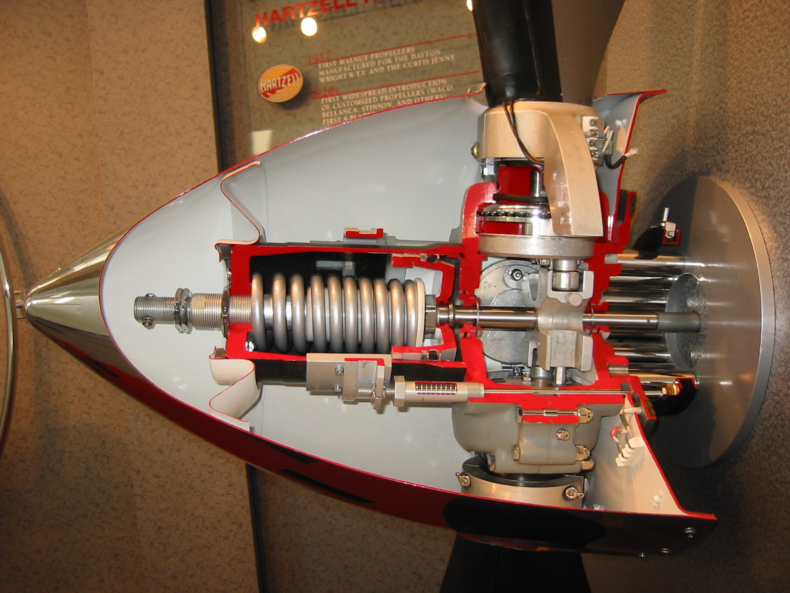
You can see that the blades are individual pieces held in the hub by a beefy retention bearing. With the prop spinning at 2600 RPM, there are more than 20 tons of centrifugal force trying to rip that blade out of the hub. As I mentioned, even if a shed blade didn’t hit the airframe as it departed, the resulting imbalance would almost certainly tear the engine off and shift the center-of-gravity to an uncontrollable location.
Suddenly, skimping on that prop maintenance doesn’t seem like such a hot idea, does it?
A spinning prop also exhibits gyroscopic properties, so every time the aircraft is pitched or yawed, immense forces twist and bend those blades. You can see an extreme example of that in a slow-motion video of a helicopter main rotor blade that I posted a while back. Rotorcraft airfoils are far less rigid than any constant-speed prop, but the principal is similar.
Aerobatic pilots know all about gyroscopic effect. If you’ve been amazed by scenes like this at an airshow and wondered how they do it, most of the spectacular maneuvers like tumbles are produced with gyroscopic effect.
The aircraft is largely being thrown about the sky from forces generated by the prop. But you pay for it with high stress on the item the prop is connected to: the crankshaft. My Pitts S-2B once broke a crankshaft due to high stress imposed on it from a two blade metal Hartzel prop after repeated snap rolls. After that, the owners elected to spring for a new light-weight, 3-blade composite MT propeller.
The takeaway is this: propellers are under high stress in flight, and although they’re quite reliable, due to their nature when things go bad they are more prone to an unrecoverable failure than a reciprocating powerplant and thus deserve even more respect than the engine they are attached to.
Okay, what shop do you like in the LA Basin?
I wouldn’t limit myself based on geography when it comes to a propeller. For one thing, you may not even have a choice. Example: if you have an MT prop on your DA40, the nearest service center that’s factory approved to work on them is, I believe, American Propeller in Redding. Even then, if certain work is needed, MT requires the prop to be sent all the way back to the factory in Germany. I recall one time we needed some work on the MTV-9 series prop hub on the Pitts, and the prop arrived there just in time for the annual Oktoberfest beer holiday… which closed the factory for a couple of weeks.
As they say, it’s all in the timing. 🙂
The Counterweight type propeller may be used to operate either as a controllable or constant speed propeller. The hydraulic counterweight propeller consists of a hub assembly, blade assembly, cylinder assembly, and counterweight assembly. The counterweight assembly on the propeller is attached to the blades and moves with them. The centrifugal forces obtained from rotating counterweights move the blades to high angle setting. The centrifugal force of the counterweight assembly is depended on the rotational speed of the propellers r.p.m. The propeller blades have a definite range of angular motion by an adjusting for high and low angle on the counterweight brackets. Controllable : the operator will select either low blade angle or high blade angle by two-way valve which permits engine oil to flow into or drain from the propeller. Constant Speed : If an engine driven governor is used, the propeller will operate as a constant speed. The propeller and engine speed will be maintained constant at any r.p.m. setting within the operating range of the propeller.